Friday, May 23, 2008

Building A Pack Canoe - Part 4: Stripping The Sides and Bottom

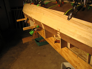
After we cut the tumblehome edge down to the scribed line and trued it up with the shoulder plane, it was time to start adding on the basswood strips that make up the rest of the hull. These strips were slightly thicker (5/32") than the walnut strips in the tumblehome area. To put the first strip on, we cut the edge of the walnut so it ran 90 degrees to each station mold. We then blended these together into a rolling bevel.  This meant that the square-edged basswood strip would fit perfectly to the walnut edge as it bent around the curves of the hull.

As with the walnut strips, we used a combination of nails, tape and clamped Plexi to get a good glue line. 

At this point, we decided it was easier to cut the rolling bevels on the strip that was to be glued on next rather than the strip that was already in place.  The next photo shows a couple of simple jigs we made to hold the strips while I planed the bevels.


The stripping proceeded rather routinely for the first 3 courses. At this point, we were able to employ another clamping aid which was simply small 2 x 3 squares of plywood with a notch cut in them so they would fit over the preceding strips. These squares were faced on one side with 80 grit sandpaper so they wouldn't slip. They were held to the station molds with a spring clamp and then tapped down with a mallet to close the gap between the strips until glue squeezed out. This method allowed us to eliminate making nail holes at each station mold.


After 8 courses of strips were glued onto both sides, we noticed that the strips were getting extremely hard to lay down at the ends because of the twist that was present

As well, we found ourselves unable to use the little clamping squares and had to resort to nails to get the strips to lie against the tight turn of the bilge.


At this time, we took a strip and bent it downward (toward the gunwales) until it fell in a fair curve without twist. We clamped it in this position at the stems and scribed a line along the top edge. Then we used my small Lie-Nielsen dovetail saw (which is actually a sweet little rip saw) to cut close to the line. Once again, we planed it down to the line with the shoulder plane. The next several strips now fell easily against the station molds without excessive twist--that is, until we got past the turn of the bilge and started stripping out the bottom.


Here is a shot of the cut we made to accommodate easier planking.


End view of our ingenious little clamping blocks.  We soon found out that they only worked where there was enough room to fit them over the previous stripping.  As we approached the keel, we had to abandon them again and go back to nailing.


Somewhere along the way, I'm not sure when, I handed Lady BK the block plane and asked her to have a go at cutting a bevel. Several minor flaws along the way had led me to a point of extreme frustration. I wanted to see if her good vision and lack of experience would trump my poor vision and skill with a block plane. All I can say is that, in the end, Lady BK did all the rest of the beveling. Didn't take long before she was doing it like a pro.  

The last several strips had quite a bit of twist in them, so much that we broke one pulling it down and had to replace it.  Some rather novel methods were needed to get these strips to lay down fair against the stems.


After several days of 4 - 6 strips per evening, we finally arrived at the point where we would begin to close the bottom of the hull. This was one of the easiest and most enjoyable parts of the stripping operation. 


First of all, the strips on the center bottom of the hull have very little twist and lie flat across the station molds. We were able to put these strips on with only a very slight bevel at certain station molds. Not only that, the strips got progressively shorter and took a lot less time to fit.

After the keel line was entirely covered with stripping, we ran a length of bright yellow Dacron fly reel backing down the exact centerline and used it to strike a perfectly straight line precisely along the keel line.  After that, I chiseled out the excess with the 2" chisel and finished with the shoulder plane.


Here is a shot of the straight run along the keel line and the space left for the closing strip.  At long last, we were ready to close the hull!


This last strip, which had to fit perfectly, took almost an hour for me to fit.


We used lengths of the green masking tape to pull the sides together in a dry run of the gluing.  When we were sure it would close properly, we put the glue on and slipped it into place on the bottom.


Here is the closing strip, all glued in.  We got plenty of glue squeeze out so we knew we had it firmly in place.


Here's a parting shot of the hull, all cleats and tape removed and lightly wet with a sponge to get an idea of what she'll look like when under varnish.


Thursday, May 22, 2008

Building A Pack Canoe - Part 3: Stripping The Tumblehome Area

The walnut strips were now ready to begin the actual stripping of the boat. The first one was placed so that its bottom edge would touch precisely at the marks on the station molds that define the upper edge of the boat (the gunwale). There were no marks for the attachment to the stems, so we bent the sheer strip up and down until we both agreed that it fell in a fair and sweet curve.

There is an old saying in boat building: "If it looks right, it is right." This pertains to the aesthetic qualities of the boat, particularly when it comes to the concept of "fairness" and "sweetness". Nowhere is this more obvious than in the lining out of the planking, and the sheer line is the most important and powerful line of all. Although we would get another chance at refining this line when we attach the gunwales, we took our time to make sure the the line was as sweet as we could get it. I'm sorry to say we totally forgot to take photos of this initial process.

We then carefully re-marked all of the lines on the station molds and stems and then clamped the sheer strip into place. I had already decided that we would not use staples to hold the strips down to the station molds. We just don't like looking at several thousand tiny black dots that tell all the world, "Hey, look... I stapled my boat together." We opted for small brads driven through cleats (so that the heads wouldn't be buried in the strips themselves) and what better tool to use than a pneumatic brad nailer.

Another decision we made was to use rolling bevels at the plank edges rather than a "bead and cove" fit. This was partially due to the fact that we were using 1/8" strips and couldn't get a set of router bits in that size, but also, we didn't see how any advantage would be gained in the complex curves. In fact, there would be a distinct disadvantage since bead and cove strips only nest together perfectly when they are 180ยบ to each other. This only happens in the flatter sections of the hull, exactly where they aren't needed. Bead and cove fits in the harder and complex curves on the ends and the bilges always have gaps.

Here I am cutting the rolling bevel to fit the preceding strip. It is all a guesstimate with a lot of trial and error fitting by eye, but it doesn't have to be perfect. 90% of the strength of the hull will be in sandwiching the wood between two layers of fiberglass and epoxy resin, so all we really need it to do is not come apart before we glass it. It is the BK way, however, to overdo everything, so we spent a great deal of time trying to get the strips to match. This became infinitely easier as time went on.


The tumble home area is wider amidships than it is at the ends. Since the strips are all 3/4" wide to begin with, we either had to taper each one throughout the length of the strip (daunting, to say the least) or we could strip it out until the entire tumblehome area was covered and then cut down to the tumblehome edge. That is what we decided to do. It also allowed us to use up some shorter strips in the areas where the tumblehome was widest and full length strips were not needed.

Here is a good shot of the tumblehome area completely stripped and awaiting cutting down. You can see the small cleats that were used to nail the strips to the station molds and also the high-tack green 3M adhesive tape we used to pull the strips together between station molds. It is expensive, but it proved to be a powerful clamping tool and quickly became our best friend.

Also in the photo are a bunch of small but very powerful Pony spring clamps. They are being used along with short strips of 1/4" Plexiglass to align the strips in spots where the tape didn't cut it (lots of them as it turned out). After a while, we felt like a seasoned surgical team as one or the other of us would reach out a hand and say, "Plexi... clamp... more tape..."

Here is how we marked out the cut for the tumblehome edge:

First, a pencil mark was made on each station mold, exactly 1" above the place where the tumblehome and the hull sides meet.

Then, a spare strip was used as a lining batten. It was placed at each mark and temporarily nailed in place. Special care had to be exercised at the stems as there was no reference point from which to measure and so its placement had to be made by eye. There was no second chance with this one like at the sheer. Whatever line we chose had better be sweet as it would be locked in place by the succeeding basswood strips and would be more than a little bit obvious if it was a "doggy" line. When we were both satisfied, we nailed the batten to the stems.

We didn't have an offset-legged compass to make the next mark and the local art store was closed, so I went ahead and "invented" this sweet little scribing block Lady BK is using in the photo. It holds a press-fit pencil that I planed dead flat on one side. The top of the block was planed down until the flat edge of the pencil was exactly 1" from it, so it always marks out a 1" space. The pencil can be slid in and out in order to get the the top edge perfectly square to the lining batten and was a breeze to use.

Next, another batten was clamped in place right on the walnut tumblehome strips and touching each mark we had made. The batten was once again sighted for fairness and a line struck.

Here is Lady BK striking the line that we would cut to. We found that a 0.5mm HB mechanical pencil gave a crisp and sufficiently dark line to follow.


Lady BK wielding the 2" chisel to split away (carefully!) the excess walnut and pare it down to within about 1/16" of the line. The rest would be taken down with my Lie-Nielsen small shoulder plane, set extremely fine and honed razor sharp. Once again, my eye would be the final arbiter of fairness.


There was no photo of the final cut curve, but here it is with a few basswood side strips attached so you can see the taper of the curve and get an idea of what all the fuss might be about achieving the sweetest possible curve here.

Friday, May 2, 2008

Building A Pack Canoe - Part 2: Final Form Assembly and Materials Thicknessing

At this time we began to cut up our wood into the proper sized strips. We made a decision to try for a graduated hull thickness. This would mean using 1/8" walnut for the tumblehome area, 5/32" basswood strips for the sides and turn of the bilge and 3/16" basswood strips for the bottom. That meant that, except for the walnut, we would have to cut all of the strips a bit thicker than 3/16" and then thickness them after the fact. We decided to use my Performax thickness sander as I haven't really played around with my Ridgid thickness planer yet and wasn't confident that I wouldn't mess up the nice wood Lady BK had picked out.

I got a real good deal on the basswood from a closeout at the local lumber yard, but I had to take what was left. There were several stained and darker pieces in the mix, but I got enough wood for more than two canoes for $100 so I could afford to let her be choosy. She wanted the lightest strips and picked out five boards that were between 8' and 14' long and of varying widths. Some of the basswood had sap streaks, small knots and splits. All of it but one board had a sideways sweep to the plank that had to be taken out first before it would ride against the fence. That meant striking a line in the position on the plank that would give us the best yield and then freehand sawing it to that line on the band saw. The walnut was all gotten out from a thick plank I had lying around and was too short for full length strips . That meant we would have to cut and glue about thirty 3" long scarf joints before the wood was thicknessed to its final dimension.

I cut the walnut into boards a bit thicker than 3/4" and then planed them flat on my Powermatic long bed jointer. After that, I laid them on their sides and cut out the strips a tad thicker than 1/8". This allowed seven 5' long strips per board. Four boards gave me 28 strips to work with.


Conventional wisdom says that the easiest way to cut the scarfs is to use a jig and a router or electric hand planer to do the actual cutting. I knew that it would take me longer to make the jig and fine tune it than it would to cut all the scarfs out by hand. So I opted for plan "B", with my favorite 2" chisel, an old W.H. Witherby (honed to arm-shaving sharp), as my weapon of choice.

Here is a photo sequence of the proper way to cut a scarf by hand:

I used a small Starrett square to measure and mark a line across the strip 3" away from the end. For illustrative purposes here, I marked the top with a yellow grease pencil, but for all the rest I just eyeballed it.

An initial cut was made about 1/3 of the way back from the end of the strip. This cut allowed me to establish the approximate angle, plus a few degrees of "fudge" factor.


A second cut is made on the opposite side, a bit more difficult since you can't see on the bottom of this cut. A mirror will help, but I really didn't need it.


Both cuts are extended back to the pencil line. Notice that the facets are slightly convex. This ensures that the plane of the scarf will not end up concave which would not make an acceptable glue line.


After a few quick passes with the 2" chisel to flatten the area, I used my Lie Nielsen 102 low angle block plane to smooth out the lumps.


Here is the finished scarf, ready for gluing. From the time I picked it up to clamp it onto the planing board until the finished scarf... 3 minutes. No fuss, no whining router or chips all over the shop. Instead, lots of tiny little shavings that made me hungry for some chocolate.


If I was going to use epoxy for the joint I would want to rough it up a bit with some sandpaper. A short strip of self sticking sandpaper (Carborundum Premium Red is the best made) fastened to a block of 1/2" Plexiglass does the job admirably. I used Titebond for the gluing, so I only included this shot for demonstration.


Here are a couple shots of my lady love learning to do the scarfing. She is battling a bit of tendinitis right now so I didn't push it with her, but she had no problem learning what was needed and she produced a couple of acceptable scarfs in almost the same time I would have spent.


Lady BK felt more comfortable sitting down so she used this vice. I found it easier and quicker to stand and use my small pattern makers vise.


Now it was time to glue all the scarfs. They not only need to be clamped properly lengthwise, they also need to be kept perfectly straight. We did four at a time on a board mounted on top of my main bench. Waxed paper was placed below them to stop them from adhering to the board and small finishing nails were used to separate them so they wouldn't get glued to each other.


Here is a view of the gluing arrangement. I left the strips in clamps while I ate lunch and then came back to do the other four.


Here is a shot of the setup used to thickness the strips. It was a very slow process. I will not use the thickness sander again for this purpose. Not only was it agonizingly slow, it left a collection of fuzz on the edges that took a lot of care and time to remove with some fine sandpaper (once again, fastened to a strip of Plexi).


Another view of the sanding operation. I was only able to put about six strips through at a time. Not only does the machine lack the power to do a bunch in one pass, the thickness from one side to the other varies by about .010" in spite of every attempt to adjust it.

As a little aside, I think this machine is a piece of crap. Another bad thing about it is that the drive belt slips off to the side as you use it. If you aren't careful it will run into the hardware mounted on the side of the machine and get torn to shreds. New drive belt? $40 plus shipping! So you have to stop the machine every ten minutes or so, loosen the belt tension and slide it back to the other side. Pain in the ass to say the least.


We didn't know where to put the finished strips when we had them all sanded, so I improvised with a bunch of bar clamps fastened to the support beam of the house. Worked better than anything I could have built. It is strong, temporary, allows us to see all the strips and they are all accessible from the side rather than having to fish them out of the end.


This shot is mostly so you get to see the station molds attached to the strongback in the background. For some reason, we forgot to take photos of the setup of the molds. We ran battens down the length in several spots to check the whole thing for fairness. At this time, we discovered to our horror that if we raised and lowered the station molds so that they were all the correct height and were plumb, the tumblehome edges on the molds did not line up to a fairly placed batten. There was no work around for this and it meant that each mold would have to be ever so slight off from plumb and that the peaks of the "vee"s along the keel line would not line up perfectly. We have a work around for that when the time comes to fair it all out, but it was either set them up so that the tumblehome edges were fair or re-draw and re-cut all of the station molds, simply not an option here.

Here is the final shot in this section. I have attached the stem mold and have screwed down the stem to it and am now cutting it to length with my Japanese ryoba saw.


Next...

In Part 3 we we cover the initial stripping of the sheer line, the stripping of the tumblehome area and the establishment and cutting of the tumblehome edge.

Cheers

Thursday, May 1, 2008

Building a small double paddle pack canoe Part 1: Design and Building Form

So here goes...

I decided to start my own blog, mostly to document the building of various boats, but also to blow off steam about the situation in the world today and what I feel is wrong with it and my existence in it. I'll try when I can to post photos of the boats and relevant building info/tips. The other stuff I'll warn you about ahead of time (orange alert) so you can skip on through. It's for my own cathartic benefit that I include it so I won't feel offended if you don't want to read about my opinions on politics, kids, illness, money etc. I do hope you will appreciate the boat related stuff at any rate because boats are what it's all about, isn't that right? Finally, this blog is a work in progress, so I expect it to evolve over time and possibly give rise to an entirely different species. Through it all, I invite you to sit down with your coffee and bagel (or what have you) and enjoy breakfast with BK.

*****


Last summer Lady BK and I went to the WoodenBoat sponsored boat show in Mystic, CT. As we walked past kayak builder/designer Nick Schade's booth, Lady BK noticed a small pack canoe on display. It was like a little jewel: 10' LOA, basswood with a walnut shouldered tumblehome and Kevlar/carbon fiber hybrid cloth on the inside, giving it the look of an old tweed-covered Fender guitar amplifier. Total weight with seat and backrest: 16#.

Lady BK was instantly in love and asked me to make one for her. Unfortunately, Nick did not have plans for sale at the time. The boat was a prototype and formal plans were still in the works. So we left with my promise to her to pursue the project later in the year when the plans were made available.

The summer went on and I ended up taking a class with traditional lapstrake boat builder Geoff Burke and built a small cedar lapstrake canoe which was raffled off at the end of the class. For the first time in my life, I won a drawing. The next day the boat was strapped to my car for the journey home. One week to the day after I got back, I nearly put my right eye out in a table saw accident.

*****

Warning, rock in the stream dead ahead...

Funny thing about eyes, you rarely look at them because you are always looking out of them. For most guys, the only time we look at our eyes in a mirror is when we do something wrong to them. So imagine my shock when I looked in the mirror to see the extent of the damage and my right eye just looked dead. The brown iris was all gray and cloudy and I had no control over any movement. There was a huge cut on the side where the block of wood hit me but no obvious cut or punture to the eye itself. No matter, all I could see out of it was a bright reddish-orange glow.

A block of pine about 2"x2"x4" weighs next to nothing, but when it comes off the top of a spinning table saw blade at about 175 MPH it has an incredible amount of energy. Yes, I was wearing impact resistant glasses, but the chunk had so much force behind it that it just slapped them off my head and carried on through on its mission of destruction: lacerated cornea and conjunctiva, torn iris, ruptured artery (traumatic hyphema), torn lens capsule, dislocated lens, damaged trabecular meshwork (regulates internal pressure), traumatic cataract, ruptured arteries on retina... I was in a lot of trouble.

You know this right away somehow, just like in the war movies when your buddy says to hang on, you're gonna make it, but you know better and just fade away into oblivion. This was no ordinary poke in the eye. In fact, I was surprised it didn't hurt more, at least right away. I've had punches to the eye that sent me down to the ground and hurt like hell, but in this type of injury it is the combo of extreme speed and mass that do the work. It is called a coup-countrecoup injury, where the eye is violently compressed and then decompressed. Same thing happens inside a race car driver's head when he gets in an accident and dies even though he had no visible injuries, or what happens to a baby in "shaken baby" syndrome. Only in this case the baby was my eye.

Turns out that the second part is the part that causes most of the damage. The energy that was stored during the instant of impact is just as instantly released, causing a mini-tsunami inside the eye, tearing things apart and wreaking general havoc. The immediate danger to vision was posed by the hyphema. 40% of the anterior chamber of the eye was filled with blood and the risk of re-rupture was great. This was to be avoided at all costs as it would likely mean the end of sight for the eye. To prevent further injury, I was instructed to lie motionless in the recliner for three weeks, only moving to go to the bathroom and to see the ophthalmologist once a day. No driving, reading, bending, lifting, grunting or even getting angry. I was put on a pharmacy's worth of drops and pills to try to get the pressure down before it destroyed my optic nerve.

I sat in that recliner and played the guitar for three weeks, re-learning every song I ever knew and playing them all until I couldn't stand them any more. Little by little, some sight returned... and then came the dreaded cataract.

I was told on the first doctor visit what the outcome might be. At best, seriously impaired vision in the eye, at worst, total blindness. A traumatic cataract isn't like an ordinary growing-old variety of cataract. Cataract surgery involves the removal of the entire natural lens in the eye and the replacement with an artificial one. In my case, the pressure inside the back of the eye pushed the gel-like fluid (vitreous humor) right on through the lens capsule and into the front chamber of the eye. Not supposed to happen. Ever. This left a gaping hole along the lens capsule that prevents the chambers from staying separated. When they pulverize the damaged lens to suck it out, there is a high risk of fragments falling back irretrievably into the posterior chamber. My doctor told me I had a 50/50 chance of developing a cataract (but I really think he knew for sure it would happen in my case) and that they would hope it progressed slowly and correct with glasses for as long as they could. He said he would not operate on the eye.

So when last November my vision started to deteriorate, I knew what was happening. My next visit confirmed it. The bad news was that is wasn't progressing slowly but was quickly leading toward blindness. A new prescription helped a bit for a while, but it kept getting worse. Since my iris was torn, it is now "blown" and won't constrict in bright light. The cloudiness of the natural lens is like looking through milky water and the blown pupil makes it look like shining a flashlight through milky water. Then there is the profound double vision and the flare around edges. What does it look like? Take two plastic sandwich bags, the ones with the textured surface, and put them over your eye. Then shine a flashlight into the eye and look around. When I do this with my left eye, things look similar to how they do in the right eye. Now add in double, triple and sometimes quadruple vision and you've just about got it.

Then there is the loss of depth perception. Not total yet because I still have some sight in the eye. The brain can do amazing things when it has to, and one of the things it can do is to take an extremely blurry image and extract info from it that I can use to perceive depth without adding all the blurriness to the image. Spooky.

The good news is that I found a guy in Philadelphia that can do a procedure to reinforce the lens capsule enough for cataract surgery to take place. I am seeing him on May 6 (six hour drive) to find out if I am a candidate. Looks very good from what I've read, but he hasn't examined me yet so I don't want to get my hopes up too high.

Well, that's off my chest. I've been wanting to tell this little tale for a while now. Not to invite you into my little pity party, but just to let you know what I've faced as I try to make this boat.

*****

Here is a photo of the body plan of the boat. It is a drawing of the shapes of the section molds that the boat will be built around:

Each point represents a set of coordinates given by the designer. In this case, they came from a table of "offsets" given in an article that Nick Schade had published in WoodenBoat magazine. The boat is the same canoe we saw at the show and is named Nymph by the designer.

After the points are all plotted out on a 1" grid, the paper is taped securely to a piece of 3/4" plywood and small finishing nails are driven through the paper and into the plywood. A thin, flexible strip of wood (I used wood, Plexiglass and Lexan) called a "batten" is pushed against the nails until it achieves a smooth "fair" curve and then a line is struck against the strip. This proceeds for all of the section molds. We were originally excited to see that Nick used a 1" grid instead of a traditional 2" grid as we assumed it would lead to greater accuracy. In reality, it only served to make the job of fairing out all the points harder, and we had to pull so many nails to get the batten to lie fair that we weren't sure which points were correct. In the end, we went for curves that seemed right and were fair to the eye. They were only small discrepancies so we weren't worried about it. We know that Nick's offsets are designed to be entered into a spreadsheet and drawn out on a plotter printer. I'm sure that the extra points fit that purpose admirable, but we felt they were unnecessary to traditional lofting (boat "lines" drawings).


After the lines were all drawn out, it was time to transfer them onto another sheet of paper. Each line represents a half-template for that particular station mold. We used pencil carbon and a marking wheel to transfer the lines onto the new sheet and then flipped it over to trace the other side. I was less than happy with the wheel method as it seemed to wander a bit. Next time I will use my light table. When each station was drawn out, it was time to glue them onto the actual plywood that the station molds were to be made from. Since this is a symmetrical design, every station but the center would be repeated fore and aft on the boat. This allowed us to nail two sheets of plywood together and cut them out simultaneously. Not only does this cut the time in half, it ensures that each end of the boat will be a perfect mirror image of the other.

In this photo, Lady BK cuts out the basic shapes from the plywood sandwich. She left them a bit shy of the line so I could finish them on the sander:


I used my oscillating spindle sander to get close to the line and Lady BK finished them off with a sharp cabinet rasp and sandpaper. We used spray adhesive to glue them onto the plywood and the upward motion of the sander lifted the edges and created a misleading fuzzy trailer of paper on the edge which we noticed in time to prevent catastrophe. I saturated the edges with cyanoacrylate glue to harden the paper at the edge. It worked well, but next time I will use hot hide glue to hold the paper down.


Here is a shot of all the station molds stacked up so you can get an idea of the boat shape to come:


The next step is to take all of the station molds and fasten them to a long box called a strongback. The box is made of 3/4" plywood and is set rigidly onto legs and then fastidiously leveled. Any subsequent operations or measurements that are done with plumbness as a reference point are dependent on getting the strongback level and secure in place. We spent quite a bit of time leveling the strongback and then placed 50# bags of landscaping stone at either end. After we were satisfied, we set about the task of measuring and marking the positions for the station molds. Nick's design calls for a 10" spacing between molds. We knew ahead of time that we wanted to make the boat a little longer for the slight increase in speed and carrying capacity that would bring. I wanted to just make an extra "0" station (the one in the middle) and leave the spacing at 10", giving an 10' 10" finished boat. This is an extremely lightweight design that calls for 1/8" planking and I wanted the molds to be close enough together that the planking would remain fair (no bumps or hollows) in between the molds. Alas, after we took the time to do make the extra mold and attach and align all the molds onto the strongback, we discovered that there was more to it than just adding the extra station. The other molds pulled the trial battens away from the center molds. We would have to adjust all the molds spacings by trial and error in order for the planking to lay flat and fair on all the molds - more trouble than it was worth. Instead, we opted for an 11" spacing that would yield an 11' boat. We chose to step up the plank thickness by 1/32" to 5/32" to compensate for the wider spacing.


Here is the clamping method we used to get the support blocks for the station molds to be screwed on tightly:


All of the support blocks have been screwed in place and await the attachment of the station molds themselves. Unfortunately, there are no photos of the initial setup but in the next sections you can clearly see the purpose of the molds as we slowly build the canoe around them.


Here I am thicknessing the eight pine strips that were to become the laminated stems. They finished out at 1/8" thick.


As you can see, all but two of them broke when we test clamped them dry over the stem mold.


At is time we made a decision to steam the wood, but we didn't have more pine on hand. Then I remembered some oversized western red cedar blocks I had on hand for classical guitar tops. I lopped off a 3" section of the outer portion of one of the chunks (leaving plenty enough width for the guitars) and Presto!... instant stem stock. These strips practically melted onto the stem forms after 5 minutes of steaming. The next day they were set and we took apart the lamination, added Titebond glue and re-clamped them.


The resulting laminated stems, after trimming to shape, weigh only 3 oz. apiece.


Next...

In Part 2 we will cover stock preparation and final mold setup.

Cheers